SLM3505
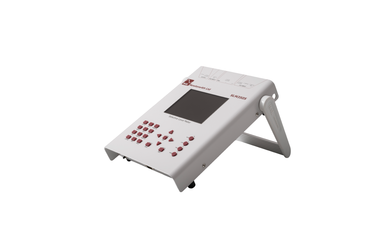
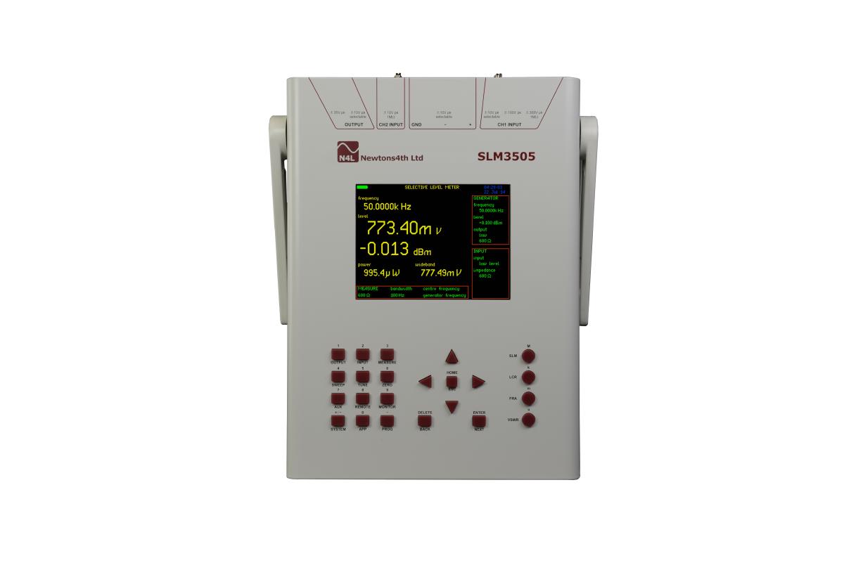
Portable Selective Level Meter with integrated Signal Generator
A field Portable Power Line Communications Analysis instrument featuring colour display and USB memory stick interface for data transfer. In addition to dual frequency selective level measurement, the N4L SLM3505 includes VSWR, Oscilloscope and Impedance (LCR) modes.
The SLM3505 was designed to provide a single instrument solution for the Electric Utility System Protection Engineer and Relay/Communications Technician, responsible for the alignment and maintenance of Power Line Carrier, Audio Tone and FSK Communications Systems. This multifunction instrument replaces all 4 existing Power Line Carrier Instruments including the signal generator into one unit, at a fraction of the cost for separate instruments, all in a compact lightweight, portable package.
Key Features
- 5Hz to 5MHz
- SLM, VSWR, Impedance (LCR) and audio frequency Oscilloscope functions
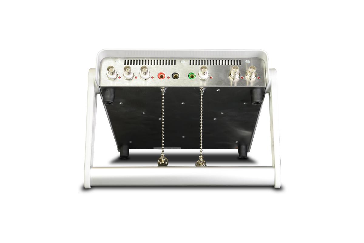
- 300Vpk Single ended floating high level input
- 10Vpk Single ended floating low level input
- Ground reference generator ±10Vpk
Applications
- Power line communications testing and maintenance
- Line trap impedance testing