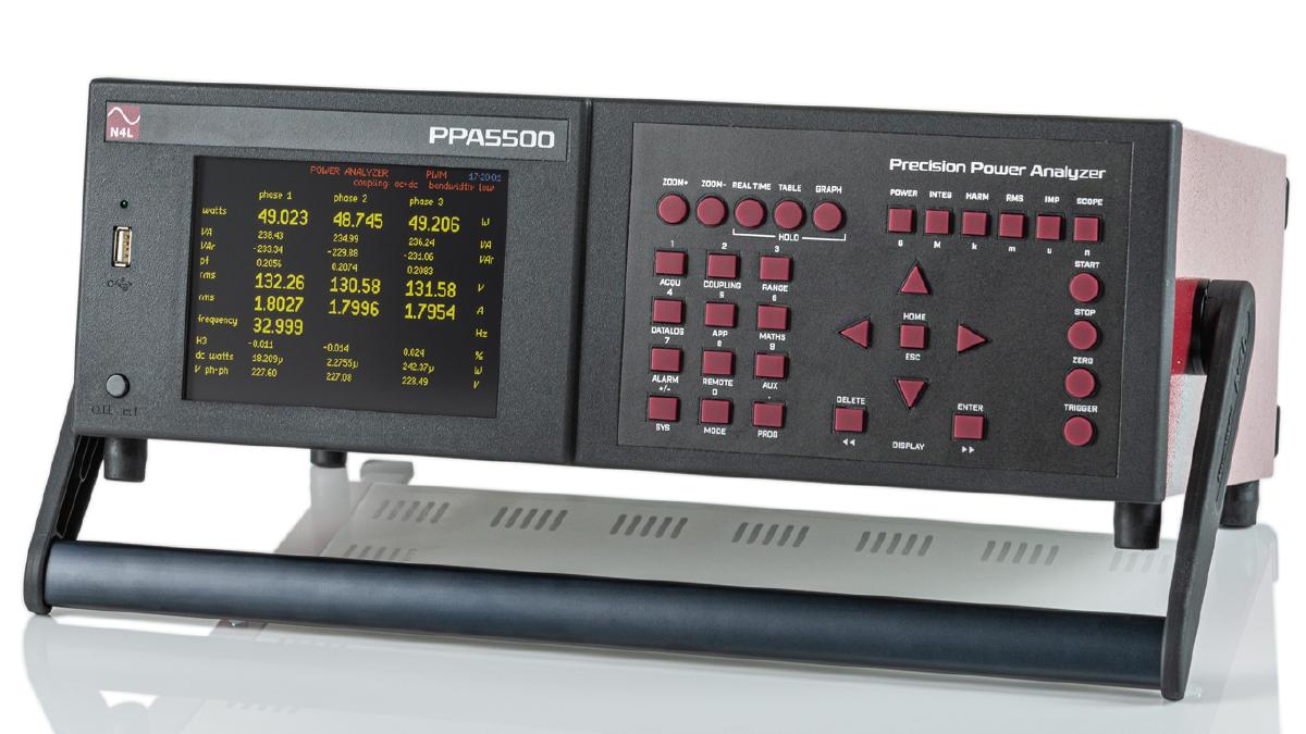
The Worlds Most Accurate Power Transformer Analyzer*
The PPA5500-TE is a high accuracy transformer power analyzer compliant to relevant testing within IEC60076-1, dedicated to the transformer industry. The PPA5500-TE builds upon years of knowledge and experience within the transformer industry bringing a power analyzer with exceptional performance. Transformer analysis requires very specific performance requirements including exceptional phase angle accuracy and repeatability. The PPA5500-TE provides market leading low power factor analysis, supplied with UKAS ISO17025 certification.
Product Images
Specification Highlights |
|
IEC Compliance | IEC60076-1 Compliant |
Voltage and Current Input Accuracy | 0.01%rdg + 0.038%rng |
45-65Hz Phase Accuracy | 0.003deg |
UKAS ISO17025 | All accuracies certified to ISO17025 |
45-65Hz Power Accuracy (Watts) Total % error, PF 1 ~ 0.5 | 0.15% |
45-65Hz Power Accuracy (Watts) Total % error, PF 0.5 ~ 0.05 | 0.23% |
45-65Hz Power Accuracy (Watts) Total % error, PF 0.05 ~ 0.02 | 0.52% |
45-65Hz Power Accuracy (Watts) Total % error, PF 0.02 ~ 0.01 | 0.55% |
Measurement Bandwidth | DC, 10mHz ~ 2MHz |
Calibration Interval | 24 Months |
Communication Ports | RS232, LAN, GPIB or USB |
Warranty | 3 Years |
Featuring the industry renowned planar shunt technology (A shunt design topology developed by N4L) and FPGA based real time no gap analysis techniques, the PPA5500 is able to provide ground breaking low power factor analysis performance.
*According to N4L market research, April 2020
ISO17025 Calibration and Verification
Every PPA5500-TE is supplied with a comprehensive UKAS ISO17025 certificate, featuring power calibration at a range of power factors from unity to 0.01, as well as a UKAS Traceable calibration certificate up to 2MHz. N4L have developed a number of bespoke power calibrators in order to verify the accuracy of every power analyzer supplied over its entire frequency range, this is surprisingly uncommon within the instrumentation industry. Furthermore, development of an ISO17025 (UKAS) accredited Closed Loop Calorimeter in partnership with Oxford University (UK) has verified the performance of the N4L custom designed power calibration rigs with a very low uncertainty level, providing absolute confidence that the wide band performance of all N4L power analyzers is market leading.
Calibration Options
1. Standard Recalibration – Included with new instruments – Included with RMA Calibration Wideband calibration (DC-2MHz) with optimisation of measurements on all ranges over the complete instrument bandwidth. Traceable to UKAS but not ‘accredited’. | 4. UKAS IEC61000 H+F Calibration – Optional with new instruments or RMA calibration UKAS accredited calibration of PPA55x1 series units that includes all prevailing type test protocols for fully compliant Harmonic and Flicker testing. This option can only be specified in addition to option 1 and option 2 calibration. |
2. UKAS (ISO17025) Calibration – Included with new instruments – Optional with RMA Calibration UKAS Accredited calibration of Voltage, Current, Phase (PF) and Power on all ranges from 55-850Hz. In addition to the calibration certificates, the PPA will be fitted with a UKAS calibration label. This option can only be specified in addition to option 1. | 5. PPA55xx-TE Calibration – Included with PPA-TE order – Optional with RMA Calibration UKAS calibration that includes a series of low power factor tests down to 0.01 PF over the frequency range of 16-450Hz. This option can only be specified in addition to option 1 and option 2 calibration |
3. System Calibration – Optional with new instruments or RMA calibration UKAS accredited calibration of a PPA together with an external sensor. This option is separate to option 1 & 2 which must both be specified in addition when system calibration is required. Note: This is end-to-end calibration of the of the PPA+sensor ‘system’ at nine N4L defined test points. (3 current levels @ 3 different frequencies) | 6. UKAS calorimeter power calibration – Optional with new instruments or RMA calibration UKAS accredited power calibration via calorimetry. Available at customer requested frequency(s) and with sinusoidal or harmonically distorted wave shapes within a frequency range of 45Hz to 2MHz. This option can only be specified in addition to option 1 and option 2 calibration |
Brochure | Documentation |
PPA5500-TE_brochure PDF, 1Mb | PPA55xx User Manual v4 PDF, 1.45Mb |
PPA55xx-Rack-Dimensions PDF, 225kb | PPA55xx Comms Manual v4 PDF, 840kb |
PPA45_5500 Brochure PDF, 6Mb | PPA55 Start up Manual v4 PDF, 3.58Mb |
PPA Datalogger User Manual PDF, 3.1Mb |
PPA Datalogger Brochure PDF, 2Mb |
Calibration Guide |
PPA5500-TE
PPA5500 Options, Software and Accessories
![]() |
Communications Interfaces: |
- Standard: LAN, USB, RS232 and GPIB Communication Ports
![]() |
Probes and Probe Accessory Options: |
- ULCP Ultra Low Capacitance Probes (Active, For use with DUT’s susceptible to capacitive loading) – 1.5pF, 1000Vrms, dc to 2MHz, 1000:1
- TT-HV 250 High Voltage Probe (Passive) – 2.5kVpk, 100:1
- TT-HVP 15HF High Voltage Probe – 15kVpk, 1000:1
- ATT20 – 20:1 Attenuator (For use when voltage probe output does not meet PPA ext. input 3Vpk max rating) – For connection to PPA ext input and external attenuating probes.
![]() |
Extension Port and Accessory Options: |
- ADI40 40 Channel Analogue <> Digital IO Interface
- PCIS – Phase controlled inrush for (Use when control of DUT source with respect to phase angle is required
![]() |
Leads, Connection and Interface Options: |
- 20A Connection lead set for one phase (supplied as standard) – 20Arated, 1.5m long + Alligator Clips
- 36A Connection lead set for one phase – 36A rated, 1.5m long + Alligator Clips
- Voltage Breakout Lead set – 3 x 2m BNC to BNC with 4mm Banana Voltage break out leads + 2 x voltage low shorting leads (For use when distance between analyser and DUT is large and HF series external shunt is being used, facilitates short voltage connections.
- Universal Breakout Box – Single Phase 10Arms Universal Breakout box
- RS232 Cable (Supplied as Standard) – 9 Pin null modem cable
- USB Cable (Supplied as standard) – 2m long A Male to B Male USB Cable
![]() |
Carry Cases: |
- PPA45/55xx Soft Carry Case – Black Nylon Padded Case with accessory space, handle and strap
- PPA45/55xx Hard Carry Case – PPA45/55xx Hard Aluminium Flight Case with accessory space, handle and lock (Ideal for Aircraft Hold)
![]() |
Rack Mounting Kit Options: |
- PPA45/55xx Rack Mounting Kit – 19″ Rack Mount Kit including brackets and fixing screws for PPA45/55xx
![]() |
Calibration and Documentation (Unit supplied with UKAS ISO17025 certificate as standard when new): |
- Standard Recalibration (ISO17025 Traceable) – Single Phase PPA (PPA5510)
- Standard Recalibration (ISO17025 Traceable) – Two and Three Phase PPA (PPA5520 & PPA5530)
- ISO17025 UKAS Calibration + Standard Calibration – Single Phase PPA (PPA5510)
- ISO17025 UKAS Calibration + Standard Calibration – Single Phase PPA (PPA5520 & PPA5530)
- PPA55xx Loan Instrument available upon request during Calibration or Repair (Available in Europe only)
- Spare set of user manuals – Hard copy of user and communications manual
![]() |
Current Measurement Options: |
- N4L HF Series Current Shunts – 1Arms ~ 500Arms Rated, DC ~ 1MHz Resistive Shunt.
- N4L WR Series Rogowski Current Transducers – 1A ~ 10000A rated, 1Hz to 1MHz Rogowski Coil
- Zero Flux Current Transducer (Current Output) – 600A rated, DC ~ 250kHz
- AC+DC Hall Effect Current Clamps – Various current ratings and bandwidths available
- AC Current Clamps – Various current ratings and bandwidths available
![]() |
PC Software (Free of charge): |
- PPALoG – Power Analysis Data Logging Software (Up to 64 Parameter simultaneous measurement, up to 12 Phases) (PPA Datalogger User Manual PDF, 3.1Mb)
- PPA Standby Power Software – IEC62301 & EN50564 Compliant (Standby Power User Manual PDF, 2Mb)
- IECSoft Harmonics and Flicker (IEC61000-3-2/3-3/3-11/3-12) Software
Application Notes and Related Articles
Video Tutorials
Tutorial 1 : Power Analyzer Turn on and External Shunt Configuration
Tutorial 2 : PWM Motor Drive Efficiency Measurements
Tutorial 2a : PWM Motor Driver Efficiency Measurements (Extended version)
Tutorial 3 : Standby Power Measurement of a USB Mains Adaptor
Tutorial 4 : AC/DC Converter Efficiency Measurements
Application Notes
For application notes please see the app note section of our Knowledge Database
Parameter | |
---|---|
Operating Range | DC, 10mHz-2MHz - 1000Vrms (3000Vpk) - 30Arms (300Apk) |
Number of Phases | 1-3 |
Voltage Input Accuracy (16 to 450Hz) %Rdg + Rng | |
20%-120% of range in 100Vpk and 300Vpk ranges (14Vrms to 250Vrms) | 0.01% + 0.038% |
Current Input Accuracy (16 to 450Hz) %Rdg + %Rng | |
20%-100% of range in 1 Apk, 3Apk and 10Apk ranges (0.14Arms to 7Arms) | 0.01% + 0.038% |
Phase Accuracy (16 to 450Hz) | |
45 - 65Hz | 0.003deg |
16 - 44Hz | 0.005deg |
66 - 180Hz | 0.006deg |
181 - 450Hz | 0.007deg |
Power Accuracy (Watts) Total % error | |
45-65Hz | |
PF 1 to 0.5 | 0.15% |
PF 0.5 to 0.05 | 0.23% |
PF 0.05 to 0.02 | 0.48% |
PF 0.02 to 0.01 | 0.55% |
16-44Hz | |
PF 1 to 0.5 | 0.17% |
PF 0.5 to 0.05 | 0.26% |
PF 0.05 to 0.02 | 0.52% |
PF 0.02 to 0.01 | 0.89% |
66-180Hz | |
PF 1 to 0.5 | 0.18% |
PF 0.5 to 0.05 | 0.28% |
PF 0.05 to 0.02 | 0.56% |
PF 0.02 to 0.01 | 1.06% |
181-450Hz | |
PF 1 to 0.5 | 0.19% |
PF 0.5 to 0.05 | 0.31% |
PF 0.05 to 0.02 | 0.64% |
PF 0.02 to 0.01 | 1.24% |
General | |
Corrected Power, normalised mean, rectified mean, form factor, crest factor, Delta-Star, Star-Delta, Cycle-by-Cycle, Harmonic and Flicker analysis | |
W, VA, VAr, V & A - rms, fundamental, AC, DC, Peak, Surge, +ve Pk, -ve Pk | |
Communication Ports | RS232, GPIB, LAN port, Rear USB Communication Port, Analogue output, Speed input, Torque input, Sync, Extension, Front USB screenshort/data storage port |
Calibration Interval | 24 Months |
Where not defined here, all specifications are equal to the standard PPA5500 | |
Standard Accessories | |
Leads | Power, RS232, USB |
Connection Cables | 36A 1.5m long 4mm stackable terminals. 1x red, 1x yellow, 2x black per phase (1x red, 1x black per phase with HC version) |
Connection Clips | 4mm terminated alligator clips – 1x red, 1x yellow and 2x black per phase (1x red, 1x black per phase with HC version) |
Instruction manual | User manual, Communications manual |
Other documents | Calibration certificate, Quick start guide |
Mechanical and Environmental | |
Display | 320×240 dot full colour TFT, White LED backlit |
Dimensions | 130H x 400W x 315D mm excluding feet |
Weight | 5.4kg (1 Phase), 6kg (3 Phase) |
Safety Isolation | 1000Vrms or DC (CATII), 600Vrms or DC (CATIII) |
Power Supply | 90 ~ 265Vrms, 50 ~ 60Hz, 40VA Max |
Operating Conditions | 5 deg to 40 deg ambient temperature (or air intake temperature when rack mounted), 20-90% Non-condensing relative humidity. |