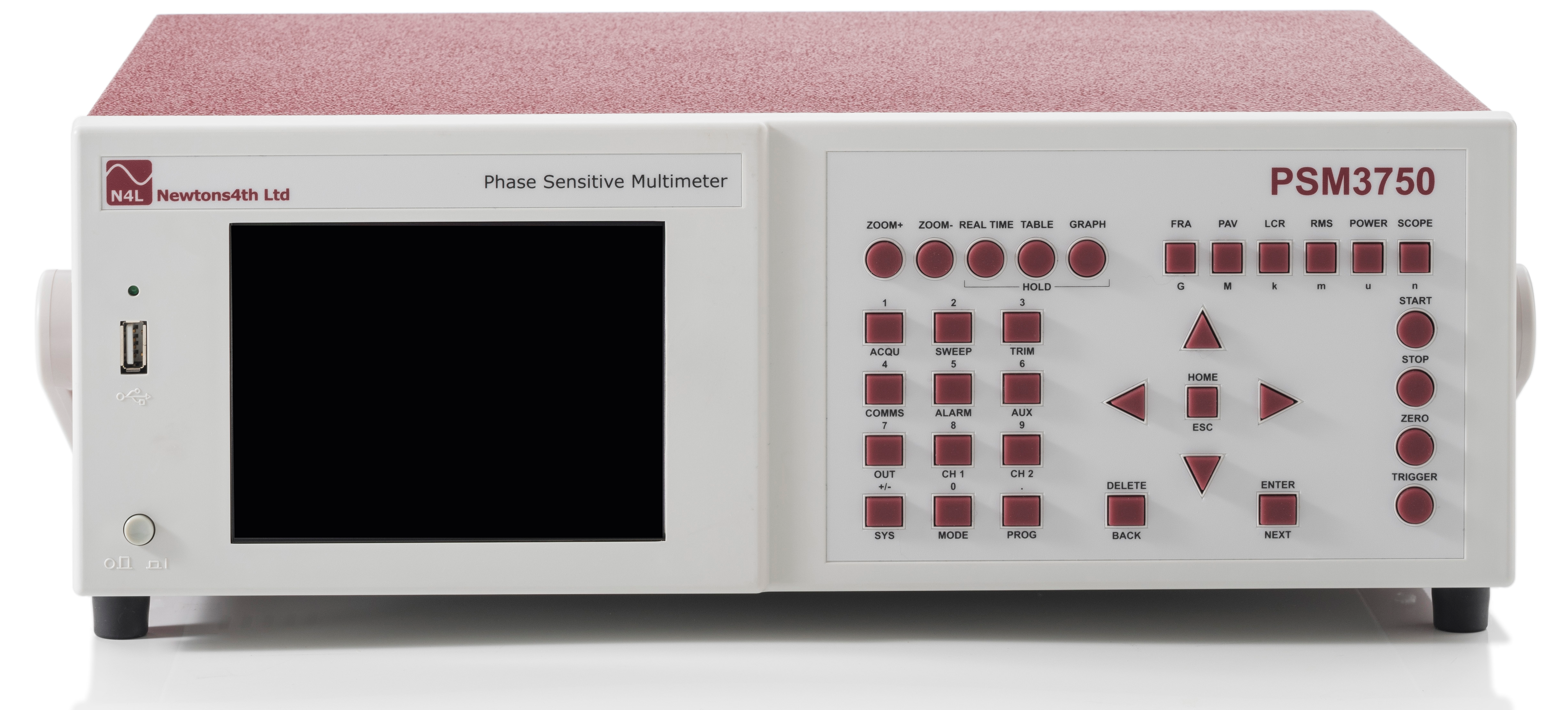
Multiple Instruments In One
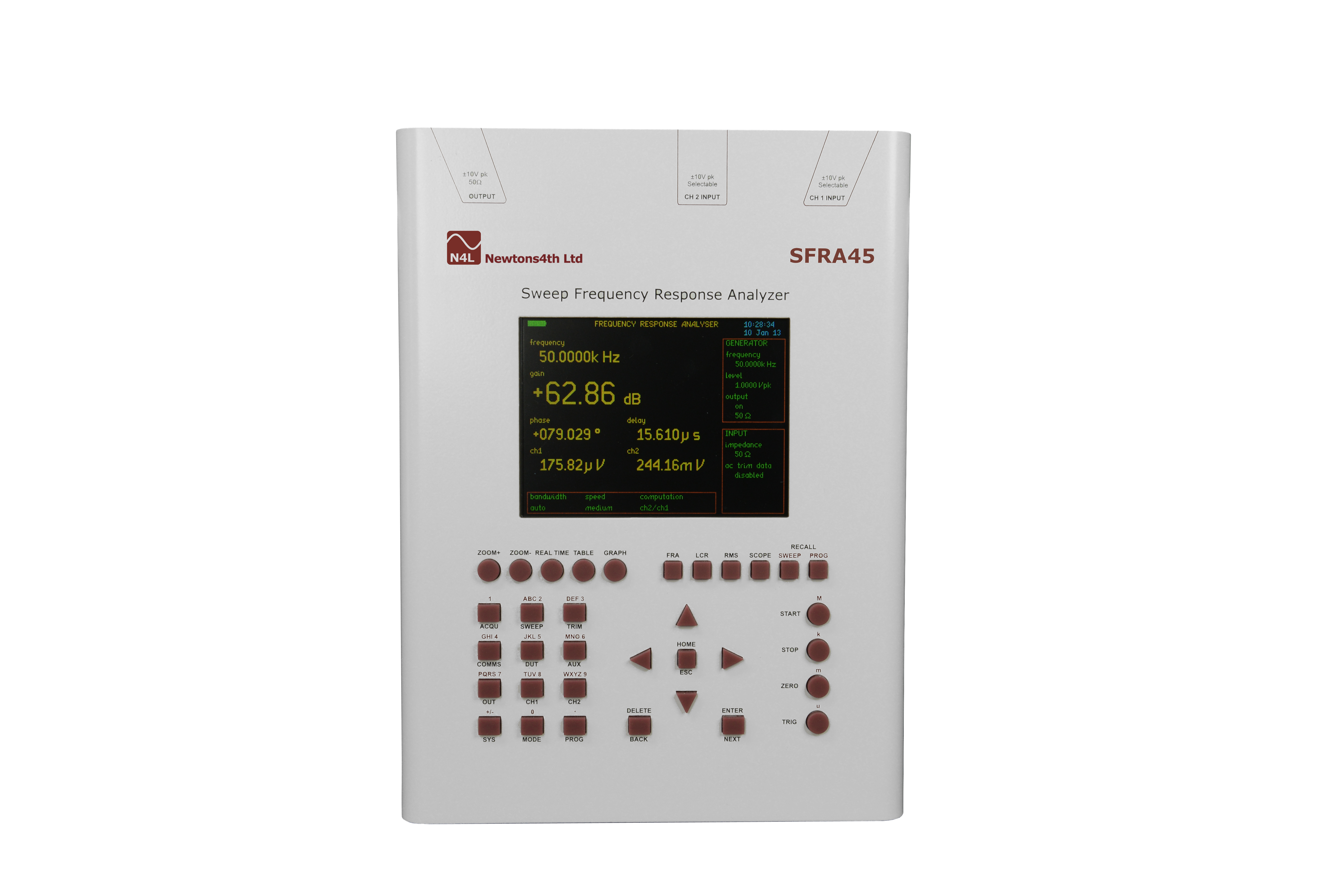
Frequency Response Analyzer
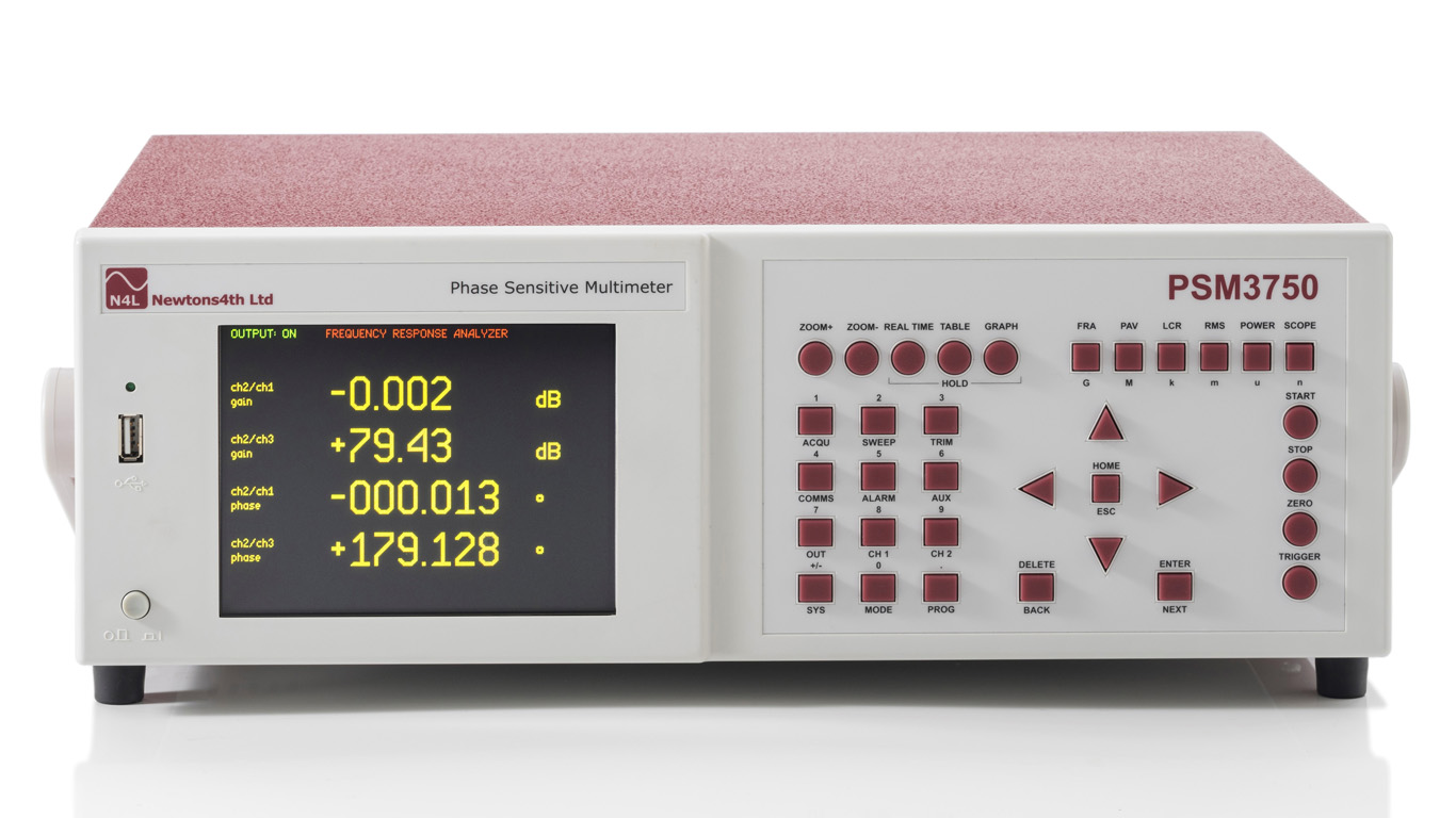
Vector Voltmeter
LCR Meter
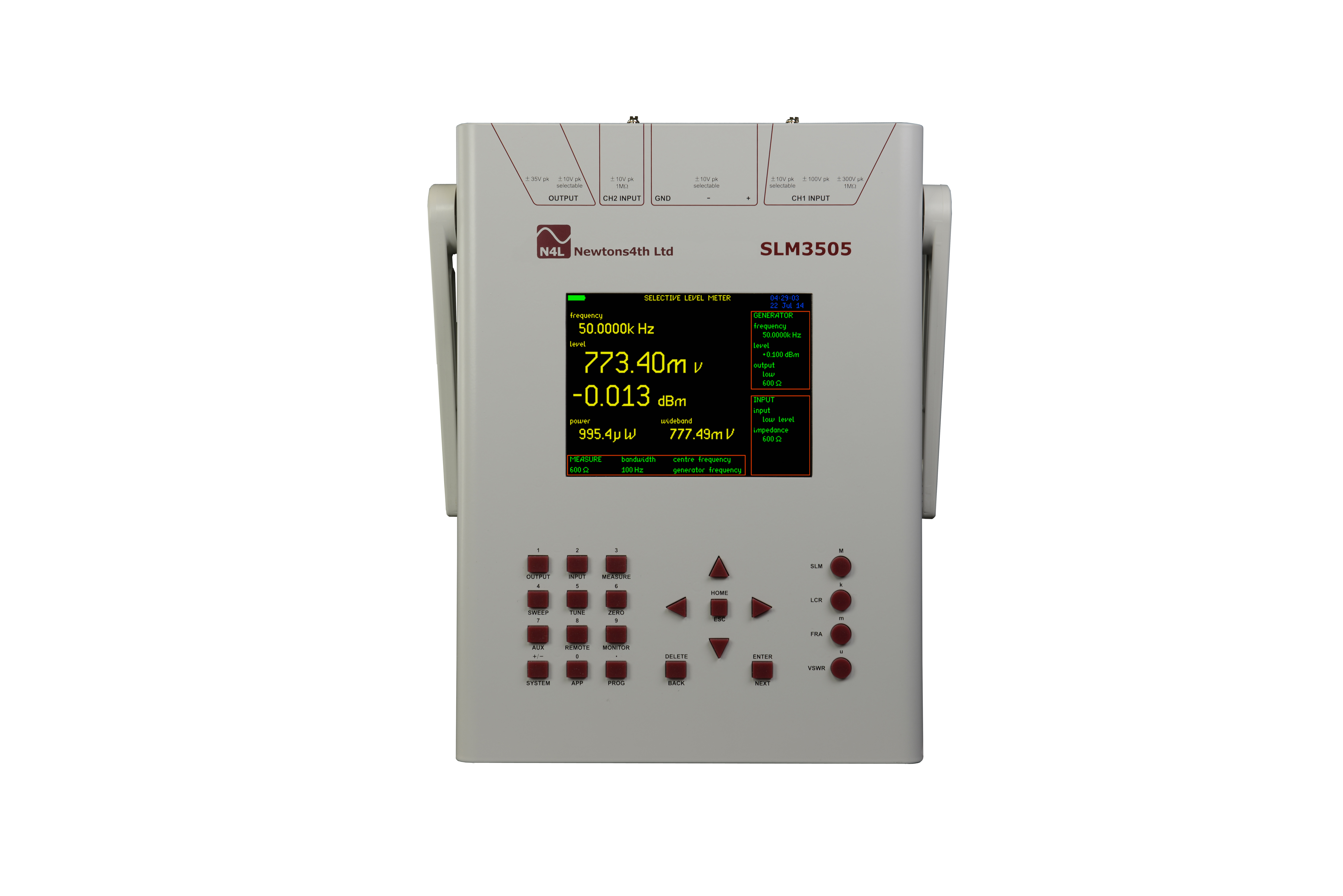
RMS Voltmeter
Power Meter
Harmonic Analyzer
Frequency Instrument Range
Learn about the range
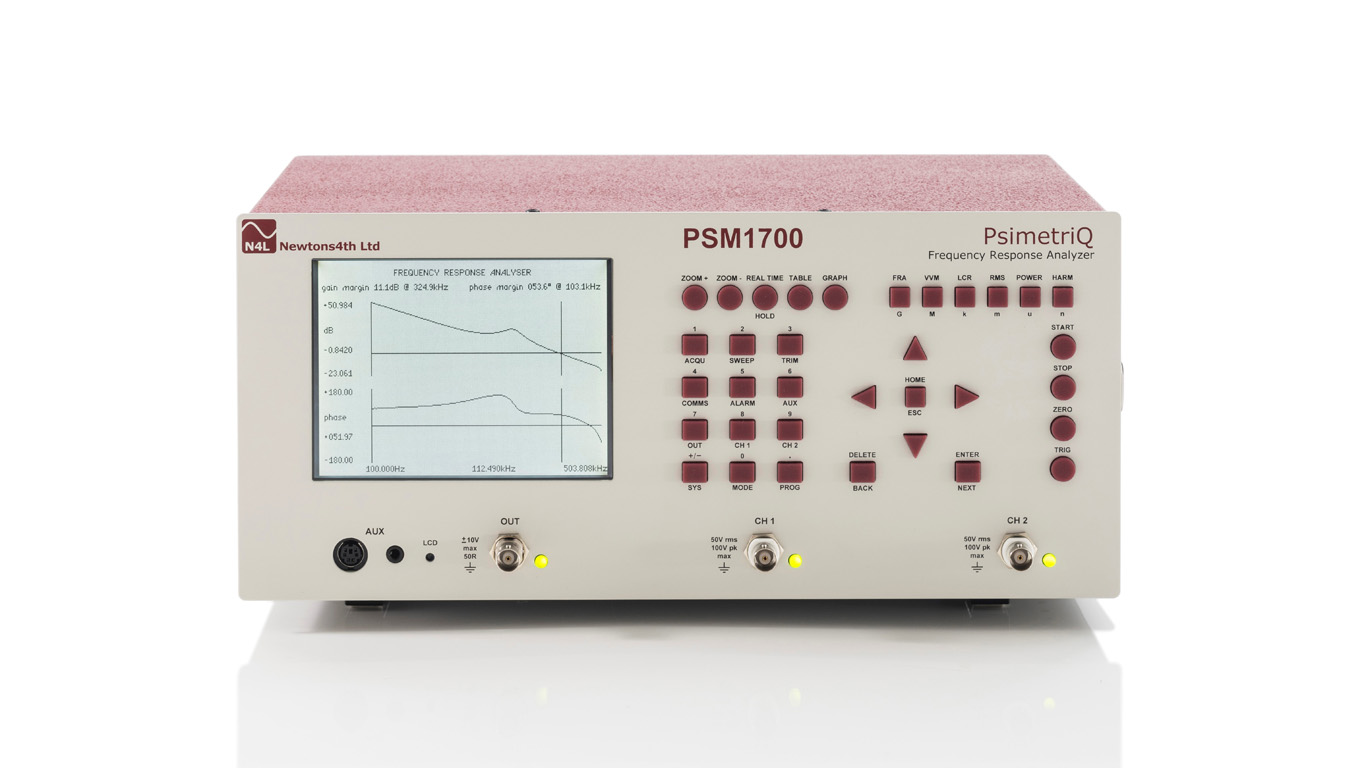
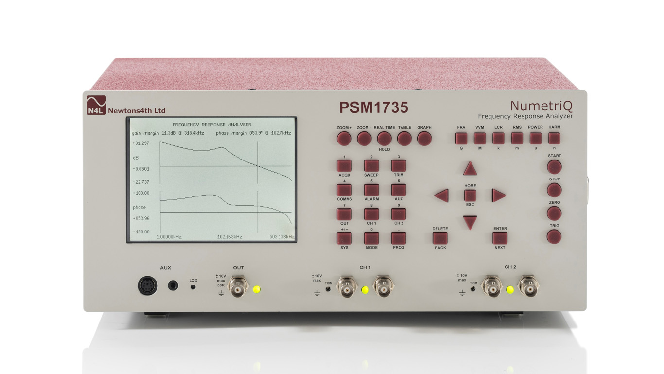
Key Feature Comparison
| PSM1700 | PSM1735 | PSM3750 | SFRA45 | SLM3505 |
|---|---|---|---|---|
| Measurements | ||||
| 10uHz ~ 1MHz | 10uHz ~ 35MHz | 10uHz ~ 50MHz | 5Hz ~ 45MHz | - |
| 0.02dB Basic Accuracy | 0.01dB Basic Accuracy | 0.01dB Basic Accuracy | 0.02dB Basic Accuracy | - |
| 0.02° Phase Accuracy | 0.02° Phase Accuracy | 0.025° Phase Accuracy | 0.025° Phase Accuracy | - |
| Inputs | ||||
| 2 Channels | 2 Channels | 2 or 3 Channels | 2 Channels | - |
| 100Vpk input | 10Vpk input | 500Vpk input | 10Vpk input | - |
| Key Applications | ||||
| PSRR Testing | RFI line filter design | Power Transformer Sweep | Communication Line Testing | |
| Component Phase Response | Low Level System Voltage | Line trap impedance |